When it comes to building DIY electronics projects, one of the most popular and versatile microcontrollers used by hobbyists and professionals alike is the Arduino NANO. Compact, affordable, and easy to program, it has become a go-to choice for a wide range of applications—from simple projects like LED blinkers to more complex tasks like automation systems or sensors. If you’ve ever used an Arduino NANO, you’ve likely encountered its pinout diagram, which provides crucial information about how each pin on the board functions. In this tutorial, we will break down the Arduino NANO pinout diagram and help you understand the role of each pin to enhance your project-building experience.
What is the Arduino NANO?
Before diving into the pinout diagram, let’s briefly understand what the Arduino NANO is. The Arduino NANO is a small, breadboard-friendly version of the popular Arduino UNO board, designed for compact and low-cost projects. It features an ATmega328P microcontroller, which is responsible for controlling the entire board and executing your code.
The Arduino NANO provides a variety of input and output pins that can be configured to interface with sensors, actuators, motors, and other external components. Understanding the function of each of these pins is crucial to developing effective and efficient projects.
The Pinout Diagram: Overview
The Arduino NANO has a total of 30 pins, each with specific functionalities. These pins can be broadly categorized into several types, which we will discuss in detail below:
• Digital I/O Pins (D0 to D13)
• Analog Input Pins (A0 to A7)
• Power Pins
• Reset Pin
• Serial Communication Pins
• Other Pins
1. Digital I/O Pins (D0 to D13)
The digital pins on the Arduino NANO are used for both input and output operations. They can read or write HIGH (5V) or LOW (0V) signals. The NANO’s 14 digital pins (from D0 to D13) provide flexibility for various applications, such as controlling LEDs, reading button presses, or driving motors.
• D0 (RX) & D1 (TX): These are the serial communication pins used for receiving (RX) and transmitting (TX) data. You will use these pins for communication with other devices via the serial protocol (such as a computer or another microcontroller).
• D2 to D13: These are general-purpose digital I/O pins, and they can be used for a variety of tasks, such as reading input signals (like from a sensor) or sending output signals (like controlling an LED or relay). Some of these pins also have special functions like PWM output or interrupt capabilities, which we’ll discuss later.
2. Analog Input Pins (A0 to A7)
The Arduino NANO includes 8 analog input pins, labeled A0 to A7. These pins are used to read analog signals, such as the output from a potentiometer, temperature sensor, or light-dependent resistor (LDR).
• A0 to A5: These analog pins can read voltages from 0V to 5V and convert them into a digital value using the Arduino’s built-in Analog-to-Digital Converter (ADC). The ADC has a 10-bit resolution, meaning the input voltage is mapped to a value between 0 and 1023.
• A6 & A7: These pins are also analog input pins, but on some versions of the NANO, they are repurposed as digital pins (D14 and D15). They still function as analog inputs, but this is something to consider depending on the specific version of your NANO board.
3. Power Pins
The Arduino NANO has several power-related pins to manage voltage supply and distribution to the board and external components.
• VCC (5V): This pin supplies the main 5V voltage to the board and connected components. You can power your NANO using an external power source or via the USB connection, which provides the 5V supply.
• GND: The ground pin is the reference voltage for all other pins and is essential for completing the electrical circuit.
• Raw: This is the voltage input pin that you can use if you are powering the Arduino NANO with an external power source, such as a battery. It will step down the voltage to 5V.
• 5V: Provides 5V power directly to your external devices or sensors that need 5V.
4. Reset Pin
• RESET: The reset pin is used to restart the microcontroller. By applying a low pulse to this pin, you can reboot the Arduino NANO, which is useful for programming or recovering from an error. This pin can be connected to a button or controlled by software to initiate a reset.
5. Serial Communication Pins
The Arduino NANO supports serial communication, which is crucial for debugging, interacting with other devices, or establishing communication with a computer. The two primary pins for serial communication are:
• D0 (RX): The receive pin, used to receive data from a connected device.
• D1 (TX): The transmit pin, used to send data to a connected device.
These pins are also used for uploading code to the Arduino NANO via the USB connection. However, if you’re using the serial pins for communication with other devices, you should be careful not to use them for programming at the same time.
6. PWM (Pulse Width Modulation) Pins
Some of the digital pins on the Arduino NANO have the capability to output a PWM signal, which is a way to simulate an analog output by rapidly switching the digital pin on and off at varying intervals. PWM is especially useful for controlling the speed of motors or dimming LEDs.
• D3, D5, D6, D9, D10, D11: These pins support PWM output, meaning you can use them for tasks like motor control or adjusting brightness levels of LEDs.
7. Interrupt Pins
Certain digital pins on the Arduino NANO also have the ability to detect external events (interrupts) and respond immediately, without waiting for the normal program flow. These interrupts are crucial in applications like detecting a button press, a sensor trigger, or a signal change.
• D2 and D3: These are the pins that support external interrupts. You can use them for tasks that need immediate attention, such as responding to an input signal or event.
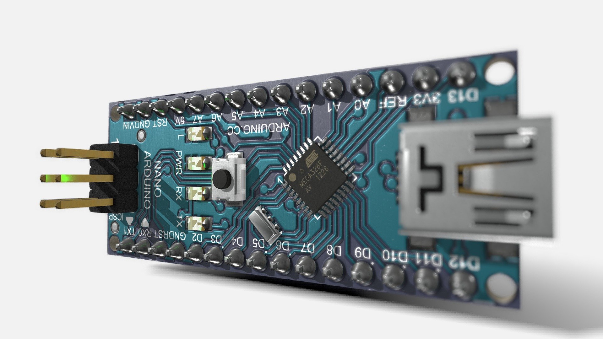
Pinout Diagram Visual
Here’s an illustration of the Arduino NANO pinout diagram to help visualize the various pins:
Conclusion
The Arduino NANO is a powerful and flexible microcontroller that offers a range of functionalities via its digital and analog pins. Understanding the Arduino NANO pinout diagram is essential for getting the most out of your projects and ensuring that your components are connected correctly.
By knowing the role of each pin, you can efficiently design circuits and write code that interfaces with sensors, actuators, and other electronic devices. The compact size of the Arduino NANO makes it an ideal choice for small and portable projects, and with a clear understanding of its pinout diagram, you can take your DIY electronics to the next level.
Happy building, and don’t forget to explore the endless possibilities with your Arduino NANO!
Written by Icey Ye from AIChipLink.
AIChipLink, one of the fastest-growing global independent electronic component distributors in the world, offers millions of products from thousands of manufacturers. Whether you need assistance finding the right part or electronic components manufacturers for your design, you can contact us via phone, chat or e-mail. Our support team will answer your inquiries within 24 hours.


